Appearance
9.2 — Motors and Generators
About 45% of the world's electricity goes into electric motors. They are in every fan, pump, compressor, lift, train and increasingly every car.
And a motor and a generator are the same machine. Turn the shaft and it produces electricity; feed it electricity and it turns the shaft. Nothing needs changing — a car's alternator and its starter motor are the same physics with the energy flowing opposite ways.
Both machines here run on the induction of Chapter 9.1, and on the force a magnetic field exerts on a current, which is Volume IV Chapter 4.5's Lorentz force. A motor and a generator are the same two facts used in opposite directions.
1. The two laws
Motor action — the force on a current in a magnetic field:
\mathbf F=I\boldsymbol\ell\times\mathbf B, \qquad F=BI\ell\sin\theta
Read it: a wire of length \ell carrying current I across a field B feels a force perpendicular to both.
Generator action — the voltage induced in a moving conductor:
e=B\ell v
Both happen at once, always. A spinning motor generates a back-EMF that opposes the supply, and a loaded generator experiences a force opposing its rotation. That opposition is not a nuisance; it is how energy conservation is enforced.
A concrete consequence. A motor at rest has no back-EMF, so the only thing limiting current is the winding resistance:
I_{stall}=\frac{V}{R}
Worked example. A 12 V motor with 0.5 Ω of winding resistance:
I_{stall}=\frac{12}{0.5}=24\ \text{A}
Once spinning at speed with 10 V of back-EMF:
I=\frac{12-10}{0.5}=4\ \text{A}
Six times more current at standstill than at speed. That is why motors trip breakers on starting, why a stalled motor burns out within seconds, and why any motor above a few hundred watts needs a starting arrangement.
A motor and a generator are the same machine with the energy running the other way, and one animation shows both.
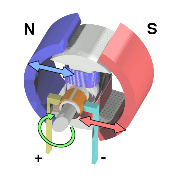
The sequence is three facts stacked, and each was established earlier in this volume.
A current in a magnetic field feels a force. That is the Lorentz force of Volume IV Chapter 4.5, F = BIL for a straight wire of length L. One side of the coil is pushed up, the other down, so the coil turns.
Halfway round, the force would reverse and fight the motion. The coil has flipped over, so what was the up-pushed side is now on the down side. Without intervention the motor would stall, rocking.
The commutator is the intervention. It is a split ring on the shaft with brushes rubbing on it, arranged so that at exactly the moment the coil passes through vertical, the connection swaps and the current through the coil reverses. The force therefore keeps pushing the same way in space even though the coil has turned over. That is the whole invention — the rest of a DC motor is engineering.
And run it backwards: turn the shaft by hand and the coil moving through the field induces an EMF by Faraday's law, so the machine becomes a generator. The commutator now does the opposite job, flipping the alternating induced voltage into a one-directional output. This is also why a spinning motor produces a back-EMF that opposes its own supply, which section 3 shows is what limits its speed.
2. The DC motor
A coil in a magnetic field, with a commutator that reverses the current every half turn.
Why the reversal is needed. The force on the coil pushes it round, but after half a turn the coil has flipped over and the same current would now push it backwards. The commutator — a split ring with brushes rubbing on it — reverses the connection at exactly the right moment, so the torque always acts the same way.
The two governing equations:
E_b=k\Phi\omega \qquad\text{(back-EMF)}
T=k\Phi I_a \qquad\text{(torque)}
Torque is proportional to current; speed is proportional to voltage. That is the DC motor's great virtue — two independent, linear controls, which is why DC motors dominated variable-speed applications for a century.
V=E_b+I_aR_a \;\Longrightarrow\; \omega=\frac{V-I_aR_a}{k\Phi}
The field connection changes the character completely:
Shunt — field winding in parallel with the armature, so \Phi is constant. Speed is nearly constant with load, dropping only by the I_aR_a term. Used where steady speed matters.
Series — field winding in series, so \Phi\propto I_a and therefore T\propto I_a^2. Enormous starting torque, and the speed rises dramatically as the load falls.
And a series motor with no load will destroy itself. With I_a small, \Phi is small, so \omega = V/(k\Phi) becomes very large — the motor runs away until it flies apart. This is why a series motor is always directly coupled to its load, never belt-driven, and it is why traction motors, which are series motors, are bolted to the axle.
Series motors are what start car engines and drive electric trains, because starting torque is exactly what both need.
Permanent magnet — the field comes from magnets, so \Phi is fixed and the behaviour matches the shunt motor with no field current to supply. Most small motors are this.
The brush problem
Brushes wear out. They are carbon blocks rubbing on a rotating copper commutator, and they need replacing periodically.
They spark. Every commutation interrupts current in an inductive winding, which by Chapter 1.5's analysis produces a voltage spike and an arc. That arc erodes the commutator, generates radio interference and is an ignition hazard in any flammable atmosphere.
They limit speed. Above about 10,000 rpm the brushes bounce and the arcing becomes destructive.
Those three problems are why the brushless motor of section 4 replaced the DC motor almost everywhere once electronics became cheap enough.
3. The induction motor
The most-used motor in the world, and its principle is genuinely elegant.
Three-phase currents in three windings spaced 120° apart produce a rotating magnetic field — the free gift of three-phase supply from Chapter 9.1.
n_s=\frac{120f}{P}\ \text{rpm}
for P poles. At 50 Hz: 3000 rpm for 2 poles, 1500 for 4, 1000 for 6.
The rotor is a cage of conducting bars, short-circuited at both ends — no windings, no brushes, no connections at all. It is often called a squirrel cage because that is what it looks like.
How it turns:
- The rotating field sweeps past the rotor bars.
- Relative motion induces a voltage in them (e=B\ell v).
- Because the bars are short-circuited, current flows.
- That current in the field produces a force (F=BI\ell).
- The rotor accelerates in the direction of the rotating field.
The essential subtlety: the rotor can never reach synchronous speed. If it did, there would be no relative motion, no induced voltage, no current and no torque. The rotor must always lag, and that lag is called slip:
s=\frac{n_s-n_r}{n_s}
Typically 2 to 5% at full load. A 1500 rpm motor actually runs at about 1440 rpm.
This is why it is called an asynchronous motor, and it is why the machine works at all — slip is not an imperfection but the operating principle.
The rotor frequency:
f_r=s\,f
At 3% slip on 50 Hz, the rotor bars see 1.5 Hz. At standstill, s=1 and they see the full 50 Hz, which is why the starting current is so large.
Why it dominates: no brushes, no commutator, no magnets, essentially nothing to wear except two bearings. A cast aluminium rotor and a stator winding. They run for decades with no maintenance, and they are cheap.
Its historical weakness was speed control. Speed is tied to supply frequency, so with a fixed 50 Hz supply the motor runs at one speed. The variable-frequency drive of Chapter 9.5 removed that limitation entirely, which is why induction motors are now used in variable-speed applications they were once excluded from.
Single-phase induction motors
A single-phase supply produces a pulsating field, not a rotating one — so a single-phase induction motor produces no starting torque at all. Spin it by hand and it runs; leave it alone and it hums and burns.
Every single-phase motor therefore has a starting mechanism that creates an artificial second phase:
Split-phase — an auxiliary winding with higher resistance, giving a current at a different phase angle. Crude, and a centrifugal switch disconnects it once running.
Capacitor-start — a capacitor in series with the auxiliary winding, shifting its current closer to 90°. Much better starting torque, and it is what a compressor or a pump uses.
Capacitor-run — the capacitor stays connected, improving efficiency and power factor continuously.
Shaded pole — a copper ring around part of each pole face delays the flux there, producing a weak sweeping field. Very poor efficiency, around 20%, and extremely cheap. Small fans and microwave turntables use it, and the low efficiency is tolerated because the power is tiny.
4. Brushless DC and permanent magnet synchronous motors
A DC motor turned inside out. The magnets are on the rotor and the windings on the stator, so the commutation must be done electronically instead of by brushes.
Position sensing by Hall effect sensors, an encoder, or — increasingly — by measuring the back-EMF in the winding that is momentarily unenergised, which is called sensorless commutation.
The controller energises the windings in sequence to keep the stator field about 90° ahead of the rotor magnets, since that is the angle producing maximum torque.
BLDC versus PMSM — the distinction is in the drive waveform:
- BLDC uses trapezoidal drive, switching in six steps per electrical revolution. Simple, and it produces slight torque ripple at each step.
- PMSM uses sinusoidal drive with field-oriented control, computing the exact currents needed. Smooth torque and higher efficiency, at the cost of much more computation.
Field-oriented control transforms the three phase currents into two components in a frame rotating with the rotor: one producing torque and one producing flux. They can then be controlled independently by two PID loops (Chapter 6.6) — which makes an AC motor as controllable as a DC one, and it is the single most important idea in modern motor drives.
Why brushless won:
- Efficiency 85 to 95%, against 75 to 85% for a comparable brushed motor.
- No wearing parts except bearings.
- Higher power density, since the heat is generated in the stator where it can escape through the housing rather than in the rotor where it cannot.
- Speeds to 100,000 rpm, limited by bearings and magnet retention rather than by brushes.
The cost is the controller, and that is why brushless motors only became common once power transistors and microcontrollers became cheap. Every drone, every electric vehicle, every modern washing machine, every hard drive and every computer fan uses one.
5. The stepper motor
Moves in discrete steps rather than rotating continuously, with a step angle of typically 1.8° — 200 steps per revolution.
Open loop. Send 200 pulses and the shaft turns one revolution, with no sensor and no feedback. That is why it is cheap and why it is popular for positioning.
And it is why it fails silently. If the load exceeds the available torque, the motor skips steps and the position is wrong from then on, with nothing to detect it. A 3D print with a layer shifted sideways is exactly this, and it is the failure mode Chapter 6.1 named when discussing open-loop control.
Microstepping drives the two windings with sinusoidally varying currents rather than switching them fully on and off, positioning the rotor between the natural steps. 1/256 microstepping gives 51,200 positions per revolution — but the holding torque at a microstep position is much lower, so the accuracy is nothing like the resolution suggests.
Torque falls with speed, because the winding inductance limits how fast the current can rise. This is why steppers are used for slow, precise positioning and never for high speed.
6. Generators
The same machines, run backwards.
Synchronous generators produce essentially all of the world's electricity. The rotor carries a DC-excited field winding, and turning it at synchronous speed induces three-phase voltages in the stator.
f=\frac{Pn}{120}
So a 2-pole generator must turn at exactly 3000 rpm for 50 Hz. Steam turbines run at exactly this speed; hydro turbines run slower and use many poles.
Grid synchronisation requires four things to match before connecting: voltage, frequency, phase and phase sequence. Connecting out of phase produces an enormous transient current and can physically destroy the machine, tearing it from its mountings.
Once connected, the generator is locked to the grid's frequency. Adding mechanical power does not speed it up — it increases the power delivered while the speed stays fixed by the grid.
Which is the mechanism behind grid frequency control. With generation exceeding demand, the whole grid accelerates slightly and frequency rises above 50 Hz. Frequency is therefore a direct measurement of the balance between generation and demand, updated continuously across an entire continent, and it is what automatic control systems watch.
The inertia point that has become topical. Large spinning generators store enormous kinetic energy, which resists sudden frequency changes and buys time for controls to respond. Wind and solar connect through inverters and provide no inertia at all, so grids with high renewable penetration have faster frequency excursions — which is why synthetic inertia from batteries and grid-forming inverters is now an active engineering requirement.
Induction generators are induction motors driven above synchronous speed, so slip is negative and power flows out. Simple and cheap, and they need the grid to supply their magnetising current, so they cannot start an isolated network on their own. Many wind turbines use them.
7. Efficiency and losses
\eta=\frac{P_{mechanical\ out}}{P_{electrical\ in}}
Where the losses go:
| Loss | Depends on | Fraction |
|---|---|---|
| Copper (I^2R) | load² | 40–60% of losses |
| Core (hysteresis + eddy) | frequency, flux | 20–25% |
| Friction and windage | speed | 10–15% |
| Stray load | load² | 5–10% |
Efficiency by size is strongly scale-dependent:
| Rating | Efficiency |
|---|---|
| under 1 kW | 60–80% |
| 1–10 kW | 80–90% |
| 10–100 kW | 90–95% |
| over 100 kW | 95–97% |
The IE efficiency classes — IE1 standard, IE2 high, IE3 premium, IE4 super premium — are now mandatory minimums in most jurisdictions.
And the economics are worth computing, because they are startling.
Worked example. A 22 kW motor running 6000 hours a year at €0.15/kWh.
At 91% efficiency (IE2): input is 24.2 kW, so annual energy is 145,000 kWh, costing €21,750.
At 94% (IE4): input is 23.4 kW, so 140,400 kWh, costing €21,060.
Saving: €690 per year. The premium motor costs perhaps €800 more, so it pays back in fourteen months and then saves money for twenty years.
And the general point that number illustrates: the motor's purchase price is around 2% of its lifetime cost. The other 98% is electricity. Which means efficiency, not price, is the correct basis for choosing one, and the fact that this is so often got wrong is why efficiency classes had to be made mandatory.
8. Choosing a motor
| Need | Choose | Because |
|---|---|---|
| Cheap, fixed speed, industrial | Three-phase induction | nothing to wear |
| Domestic appliance, single phase | Capacitor-start induction | needs the starting mechanism |
| High efficiency, variable speed | PMSM with a drive | best efficiency and control |
| Precise positioning, low speed | Stepper or servo | open or closed loop positioning |
| High starting torque | Series DC or induction with a drive | torque at zero speed |
| Very high speed | Brushless | no brushes to bounce |
| Lowest cost, tiny power | Shaded pole | efficiency is irrelevant at 20 W |
The industry's direction is clear. Almost everything is moving to permanent magnet synchronous motors driven by inverters with field-oriented control, because the efficiency gain pays for the electronics many times over and the control quality is far better.
The one constraint slowing it is that the best magnets need rare earth elements — neodymium and dysprosium — whose supply is concentrated in a few countries. This has driven genuine engineering effort into magnet-free alternatives: synchronous reluctance motors, which use a specially shaped steel rotor with no magnets at all, and switched reluctance motors. Both achieve efficiency close to permanent magnet machines with no rare earths, at the cost of more complex control.
Chapter 9.3 covers where the electricity comes from when there is no grid, and why a battery's behaviour is so much more complicated than a voltage source with a series resistor.
Every formula above, built from scratch
None of the results in this chapter are worth memorising, because each one can be rebuilt in under a minute from something simpler. What follows is that rebuilding, one result at a time, so the formula and the reason for it sit on the same page as the explanation that needed them.
Motors and generators
F=BI\ell\sin\theta \qquad\text{(motor action)}
e=B\ell v \qquad\text{(generator action)}
Both always occur together, which is how energy conservation is enforced.
DC machines
E_b=k\Phi\omega, \qquad T=k\Phi I_a
V=E_b+I_aR_a \;\Longrightarrow\; \omega=\frac{V-I_aR_a}{k\Phi}
I_{stall}=\frac{V}{R_a}
A 12 V motor with 0.5 Ω draws 24 A at standstill and 4 A at speed — the six-to-one ratio that trips breakers and burns stalled motors.
Series motor: \Phi\propto I_a so T\propto I_a^2, and \omega\to\infty as load \to0. Never run one unloaded.
Induction motors
n_s=\frac{120f}{P}\ \text{rpm}
s=\frac{n_s-n_r}{n_s}, \qquad f_r=sf
Slip cannot be zero, because zero relative motion means no induced voltage, no rotor current and no torque.
T\propto\frac{sR_2}{R_2^2+(sX_2)^2}
Maximum torque at s=R_2/X_2.
P_{gap}=\frac{P_{mech}}{1-s}, \qquad P_{rotor\ loss}=s\,P_{gap}
Read the last one: at 3% slip, 3% of the air-gap power is lost in the rotor. That is why high-slip operation runs hot.
Efficiency
\eta=\frac{P_{mech}}{P_{elec}}
Loss shares: copper 40–60%, core 20–25%, friction and windage 10–15%, stray 5–10%.
Lifetime cost: for a motor running continuously, purchase price is around 2% of lifetime cost and electricity is the rest. A 3 percentage-point efficiency gain on a 22 kW motor saves about €690 a year at €0.15/kWh over 6000 hours.
What the next chapter fixes
Motors and generators need a supply to work from or a load to feed. Chapter 9.3 covers the store that sits between them: what is happening chemically inside a cell, why the voltage is what it is, why capacity fades, and what "fast charging" is trading away.