Appearance
1.5 — Friction, Circular Motion and Fictitious Forces
Push a heavy crate. Nothing happens. Push harder. Still nothing. Push harder again and suddenly it lurches into motion, and now it takes less effort to keep it sliding than it took to start it.
Three separate things happened there, and the laws from Chapter 1.4 do not on their own explain any of them. Friction is not one force with one formula; it has two distinct regimes with a discontinuity between them, and knowing which regime you are in is most of the skill.
Then there is the other gap. A car going round a roundabout at a steady 40 km/h is accelerating — its direction is changing, so its velocity is changing — and the acceleration points sideways, towards the centre, which is a direction the car is not moving in at all. That needs deriving, because nothing so far explains where it comes from or how big it is.
Friction: what is actually happening down there
Two surfaces in contact never touch across their whole apparent area. Under a microscope both are ranges of peaks and valleys, and they meet only at the tips of the tallest peaks. The real contact area is a tiny fraction of the area you can see — often a thousandth of it — and at those tiny contact patches the pressure is enormous, high enough that the material yields and the surfaces cold-weld together in microscopic spots.

Sliding means breaking those welds and forming new ones continuously. That is the resisting force, and it is why friction generates heat: the energy goes into tearing and reforming bonds.
This picture explains the one fact about friction that always seems wrong. Friction does not depend on the apparent contact area. A brick slid on its narrow edge and on its broad face experiences the same friction. The reason: pressing the same weight through a smaller apparent area raises the pressure, which squashes the peaks flatter, which increases the real contact area in exactly the proportion needed to cancel the change. Halve the apparent area, double the pressure, and the number of welded spots stays the same.
What friction depends on instead is how hard the surfaces are pressed together — the normal force N.
Static friction: the force that adjusts itself
While the crate is not sliding, friction is doing something unusual for a force: it takes whatever value it needs to.
Push with 50 N and the crate does not move, so the net force must be zero, so friction is 50 N backwards. Push with 100 N and it still does not move, so friction is now 100 N. Static friction is not a fixed number; it is a response, and it matches whatever you apply, up to a limit.
That limit is:
f_s \le \mu_s N
Read aloud: static friction is less than or equal to mu-s times N, where \mu_s is the coefficient of static friction, a dimensionless number that depends on the pair of materials. The inequality is the whole point of the formula, and writing f_s = \mu_s N when the body is not on the verge of slipping is the most common friction error there is. That equality holds at one moment only: the instant of impending motion.
Kinetic friction: once it is sliding
The moment the crate breaks free, the welds no longer have time to form fully before being torn apart again, so the resistance drops. Now friction has a definite value:
f_k = \mu_k N
with \mu_k < \mu_s for essentially every material pair. This is why the crate lurches: at the breakaway instant your push exceeds \mu_s N, friction immediately drops to \mu_k N, and the leftover force accelerates the crate suddenly.
Kinetic friction is very nearly independent of sliding speed over ordinary ranges, which is a convenient and slightly surprising experimental fact rather than something derivable.
| Static | Kinetic | |
|---|---|---|
| When | Not sliding | Sliding |
| Value | Whatever balance needs | \mu_k N |
| Formula | f_s \le \mu_s N | f_k = \mu_k N |
| Direction | Opposes attempted motion | Opposes actual motion |
Typical coefficients: rubber on dry tarmac \mu_s \approx 0.9; rubber on wet tarmac \approx 0.5; steel on steel \approx 0.6 dry and \approx 0.1 oiled; ice on ice \approx 0.1; joint cartilage in your knee \approx 0.003, which is slipperier than anything engineering has built.
The one that surprises everyone: friction is what pushes a car forward
The tyre of an accelerating car is not sliding on the road. The bottom of a rolling wheel is instantaneously stationary relative to the ground — Chapter 1.8 proves this — so the friction acting there is static friction, and it points forwards.
Here is why. The engine turns the wheel, so the tyre's contact patch tries to push backwards against the road. Static friction resists that attempted backward slipping, so it acts forwards on the tyre, and that forward force is what accelerates the car. Nothing else could: gravity is vertical, the normal force is vertical, and air resistance points backwards.
That is why anti-lock brakes exist. Once a wheel locks and skids, you have dropped from static friction (\mu_s \approx 0.9) to kinetic (\mu_k \approx 0.7), so your braking force falls by around 20%, and worse, a sliding tyre gives you no steering at all. ABS pulses the brakes to keep the tyre just below the slipping threshold, in the static regime where the grip is highest.
Worked example: the block on a slope
A block sits on a plank. You slowly tilt the plank. At what angle does it start to slide?
Set up axes along and perpendicular to the slope, not horizontal and vertical. This is the choice that makes the problem three lines instead of fifteen, because the acceleration (when it comes) is along the slope, and one axis should always lie along the acceleration.
At angle \theta, the weight mg points straight down, which in slope coordinates has:
- a component into the slope of mg\cos\theta
- a component down the slope of mg\sin\theta
Why cosine goes with the perpendicular and sine with the along-slope direction, since getting this backwards is the most common error in the whole of mechanics. Tilt the slope and the block's weight vector does not move — it always points straight down. What moves is the slope, and with it the two axes you are resolving onto. The angle between the weight and the inward normal is exactly \theta, the same as the slope's angle, because both are measured from the vertical and the horizontal respectively and those two rotate together.
If that argument does not settle it, the two extreme cases will, and they take three seconds to check every time:
- \theta = 0, the plank is flat. All the weight should press into it and none should pull the block along. And indeed \cos 0 = 1 gives the full mg pressing in, while \sin 0 = 0 gives nothing along.
- \theta = 90°, the plank is vertical. Nothing presses into it and the block is in free fall. And \cos 90° = 0, \sin 90° = 1.
The assignment is forced. Never memorise it — check the extremes.
How the angle changes each quantity, which is the thing the diagram is really for:
| Slope angle | N = mg\cos\theta | Down-slope pull mg\sin\theta | Max friction \mu_sN |
|---|---|---|---|
| 0° | mg | 0 | \mu_s mg |
| 15° | 0.97mg | 0.26mg | 0.97\mu_s mg |
| 30° | 0.87mg | 0.50mg | 0.87\mu_s mg |
| 45° | 0.71mg | 0.71mg | 0.71\mu_s mg |
| 60° | 0.50mg | 0.87mg | 0.50\mu_s mg |
| 90° | 0 | mg | 0 |
Read the two middle columns against each other. As the slope steepens, the force trying to slide the block grows and the force pressing it down — which is what generates the friction holding it — shrinks. They move in opposite directions, and that is why slipping is not a gradual affair: the margin closes from both ends at once. At 45° they are exactly equal, which is why \mu_s = 1 is the coefficient that just barely holds a block on a 45° slope.
Perpendicular to the slope there is no acceleration, so:
N = mg\cos\theta
This is the promised proof that the normal force is not the weight in general. On a slope it is smaller, and it gets smaller as the slope steepens.
Along the slope, the block is on the verge of slipping when the driving component exactly equals the maximum static friction:
mg\sin\theta = \mu_s N = \mu_s\, mg\cos\theta
The mg cancels from both sides — so the answer does not depend on the mass at all, and a feather and an anvil slide at the same angle:
\frac{\sin\theta}{\cos\theta} = \mu_s \quad\Longrightarrow\quad \boxed{\tan\theta_{\max} = \mu_s}
This angle is called the angle of repose, and it gives you a way to measure \mu_s with a plank and a protractor. It is also why a pile of dry sand always forms a cone with the same slope no matter how much sand you pour: grains roll down until the surface angle drops to \tan^{-1}\mu_s, and then they stop.
Worked example: the block that is already sliding
A 4.0 kg block is released on a 35° slope with \mu_k = 0.25. Find its acceleration, its speed after sliding 3.0 m, and then find what happens if it is instead given an initial push up the slope at 6.0 m/s.
Going down. Perpendicular to the slope there is no acceleration:
N = mg\cos35° = 4.0\times9.81\times0.8192 = 32.14\ \text{N}
Friction opposes the motion, so for a block sliding down it points up the slope:
f_k = \mu_kN = 0.25\times32.14 = 8.04\ \text{N}
Along the slope, taking down-slope as positive:
ma = mg\sin35° - f_k = 4.0\times9.81\times0.5736 - 8.04 = 22.51 - 8.04 = 14.47\ \text{N}
a = \frac{14.47}{4.0} = 3.62\ \text{m/s}^2
Speed after 3.0 m, from v^2 = u^2+2as with u = 0:
v = \sqrt{2\times3.62\times3.0} = \sqrt{21.7} = 4.66\ \text{m/s}
Now sliding up. Everything about the geometry is unchanged, so N and f_k have exactly the same values. What changes is friction's direction: the block is moving up, so friction acts down the slope, on the same side as gravity's component. Both now oppose the motion:
ma = -\left(mg\sin35° + f_k\right) = -(22.51+8.04) = -30.55\ \text{N}
a = -7.64\ \text{m/s}^2
Distance travelled before stopping, from v^2 = u^2+2as with v = 0:
0 = 36 - 2\times7.64\times s \quad\Longrightarrow\quad s = \frac{36}{15.28} = 2.36\ \text{m}
Does it then slide back down? Only if gravity's pull beats the maximum static friction. Taking \mu_s \approx \mu_k:
mg\sin35° = 22.51\ \text{N} \quad\text{versus}\quad \mu_sN = 8.04\ \text{N}
Gravity wins comfortably, so yes, it slides back — and it comes back down with the 3.62 m/s² acceleration from the first part, arriving at the starting point at \sqrt{2\times3.62\times2.36} = 4.13\ \text{m/s}, slower than the 6.0 m/s it left with.
What to notice, and it is the point of the whole example. The deceleration going up (7.64) is more than twice the acceleration coming down (3.62), because friction changes sides while gravity does not. That asymmetry is why a block always returns slower than it left, and it is the mechanical version of the energy statement in Chapter 1.6: friction takes energy out on both legs of the journey, never puts any back.
Worked example: pushing a box at an angle, and why pulling beats pushing
A 30 kg crate on a floor with \mu_s = 0.45. You can either push it with a force angled 25° downwards, or pull it with the same force angled 25° upwards, as with a handle or a rope. Which needs less force to get it moving?
The reason this is not obvious is that the applied force does two things at once: part of it drives the crate along, and part of it changes how hard the crate presses on the floor — which changes the friction you are fighting.
Pushing down at angle \theta. The vertical component of your push adds to the weight:
N = mg + F\sin\theta
The horizontal component must beat friction to start it moving:
F\cos\theta = \mu_s(mg+F\sin\theta)
Gather the F terms on the left:
F\cos\theta - \mu_sF\sin\theta = \mu_smg
F = \frac{\mu_smg}{\cos\theta - \mu_s\sin\theta}
With \mu_s = 0.45, m = 30 kg, \theta = 25° (\cos = 0.9063, \sin = 0.4226):
F = \frac{0.45\times30\times9.81}{0.9063 - 0.45\times0.4226} = \frac{132.4}{0.9063-0.1902} = \frac{132.4}{0.7161} = 185\ \text{N}
Pulling up at the same angle. Now the vertical component reduces the normal force:
N = mg - F\sin\theta
F\cos\theta = \mu_s(mg - F\sin\theta)
F = \frac{\mu_smg}{\cos\theta + \mu_s\sin\theta} = \frac{132.4}{0.9063+0.1902} = \frac{132.4}{1.0965} = 121\ \text{N}
Pulling needs 121 N against pushing's 185 N — 35% less effort, for the same crate on the same floor at the same angle. Notice the two answers differ only in a single sign in the denominator, and that sign is entirely about whether your force is helping the floor hold the crate or helping to lift it.
This is why every heavy suitcase has a handle at the top rather than a bar at the back, why a horse-drawn plough is pulled by traces angled upwards, and why the sensible way to move a wardrobe is to pull it towards you rather than shove it away.
And there is a best angle. Minimising the pulling formula means maximising its denominator \cos\theta+\mu_s\sin\theta. Differentiating with respect to \theta and setting the result to zero gives -\sin\theta + \mu_s\cos\theta = 0, so:
\boxed{\tan\theta_{\text{best}} = \mu_s}
The same relationship as the angle of repose, arrived at from a completely different question. Here \theta_{\text{best}} = \tan^{-1}0.45 = 24.2° — so the 25° in the problem was almost exactly optimal, and pulling at that angle needs 120.9 N, the least possible. Pull too shallow and you gain no relief from the load; pull too steep and you waste your effort lifting instead of dragging.
Circular motion, and where the acceleration comes from
Now the second gap. Something moving in a circle at constant speed is accelerating, because velocity is a vector and its direction is changing. We need the size and direction of that acceleration.

Deriving the centripetal acceleration
Take a particle going round a circle of radius r at constant speed v. Consider two instants separated by a small time \Delta t, during which the particle sweeps through a small angle \Delta\theta.
Step 1 — the position vectors. The two position vectors both have length r and the angle between them is \Delta\theta.
Step 2 — the velocity vectors. The velocity is always tangent to the circle, so it is always perpendicular to the position vector. If the position vector turns through \Delta\theta, then the velocity vector — being rigidly attached at 90° to it — turns through exactly the same \Delta\theta. Both velocity vectors have length v.
Step 3 — the change in velocity. Draw the two velocity vectors from a common point and connect their tips: that connecting arrow is \Delta\vec{v}. It forms an isosceles triangle with two sides of length v and an apex angle \Delta\theta.
Step 4 — the length of \Delta\vec{v}. For a small angle, the chord of an isosceles triangle is very nearly the arc, so
|\Delta\vec{v}| \approx v\,\Delta\theta
(This is the small-angle approximation, and it becomes exact in the limit \Delta\theta \to 0. Volume II, Chapter 5.1 handles the limit properly; the short version is that \sin x \to x as x\to 0, so chord and arc converge.)
Step 5 — divide by time.
a = \lim_{\Delta t\to 0}\frac{|\Delta\vec{v}|}{\Delta t} = v\,\lim_{\Delta t\to 0}\frac{\Delta\theta}{\Delta t} = v\,\omega
where \omega = d\theta/dt is the angular velocity in radians per second.
Step 6 — relate \omega to v. In time \Delta t the particle covers arc length r\Delta\theta at speed v, so v\Delta t = r\Delta\theta, giving v = r\omega.
Substituting \omega = v/r:
\boxed{a_c = \frac{v^2}{r} = \omega^2 r}
Step 7 — the direction. As \Delta\theta \to 0, the isosceles triangle's base angles both approach 90°, so \Delta\vec{v} becomes perpendicular to the velocity. Perpendicular to a tangent is along the radius, and drawing the triangle carefully shows it points inwards. Hence the name: centripetal, from Latin for "centre-seeking".
The result is worth sitting with. The acceleration is perpendicular to the velocity at every instant. Chapter 1.6 will show that a force perpendicular to motion does no work, which is exactly why the speed can stay constant while the acceleration is never zero.
Centripetal force is not a new force
By Newton's second law, that acceleration needs a net force:
F_c = \frac{mv^2}{r}
But — and this matters more than the formula — there is no such thing as "centripetal force" in the list of forces. It is a job description, not a kind of force. Something real must be doing the pointing-inwards, and identifying what is the whole of the physics:
| Situation | What actually supplies it |
|---|---|
| Car on a flat bend | Static friction from the road |
| Ball on a string | Tension in the string |
| Moon orbiting Earth | Gravity |
| Electron in a magnetic field | Magnetic force |
| Ball in a spinning bucket | Normal force from the bucket wall |
| Rollercoaster loop, at the top | Gravity plus the track's normal force |
If you write "centripetal force" on a free-body diagram, you have made an error. The diagram gets tension, or friction, or weight — and then those add up to mv^2/r.
Worked example: the maximum speed round a flat bend
A car takes a flat bend of radius 50 m. The tyre–road coefficient of static friction is 0.80. How fast can it go before it slides?
Free-body diagram, viewed from behind the car. Vertically: weight mg down, normal N up, no vertical acceleration, so N = mg. Horizontally: friction, pointing towards the centre of the bend, and that is the only horizontal force there is.
The car is on the point of sliding when friction reaches its maximum:
\mu_s N = \frac{mv^2}{r}
\mu_s\, mg = \frac{mv^2}{r}
The mass cancels again:
v_{\max} = \sqrt{\mu_s\, g\, r} = \sqrt{0.80 \times 9.81 \times 50} = \sqrt{392} = 19.8\ \text{m/s} = 71\ \text{km/h}
Now change one number: it rains, and \mu_s drops to 0.40. Then v_{\max} = \sqrt{196} = 14.0\ \text{m/s} = 50\ \text{km/h}. Halving the grip does not halve the safe speed — it divides it by \sqrt2, because v goes as the square root of \mu. That is a more forgiving relationship than you might fear, and it is still a 30% cut.
Note what did not appear in the answer: the mass. A loaded truck and an empty one slide at the same speed on the same bend, because more mass needs more centripetal force and provides proportionally more friction. (Real tyres complicate this — grip is not perfectly proportional to load — but the physics-class answer is genuinely close.)
Worked example: the banked curve
Motorway bends and racetracks are tilted inwards. Why, and by how much?
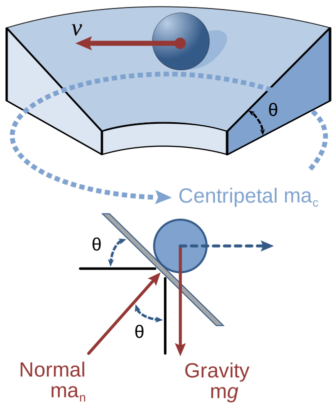
Bank the road at angle \theta and consider the ideal case where friction contributes nothing — the speed at which the bank alone does the job. Now the normal force is perpendicular to the tilted road, so it is tilted from vertical by \theta, and it has two components:
- vertical: N\cos\theta
- horizontal, pointing towards the centre: N\sin\theta
Vertically there is no acceleration (the car is not rising or sinking):
N\cos\theta = mg \tag{1}
Horizontally, the inward component supplies the centripetal force:
N\sin\theta = \frac{mv^2}{r} \tag{2}
Divide (2) by (1). The N cancels, and so does the m:
\frac{N\sin\theta}{N\cos\theta} = \frac{mv^2/r}{mg} \quad\Longrightarrow\quad \boxed{\tan\theta = \frac{v^2}{rg}}
For a bend of radius 200 m designed for 90 km/h (25 m/s):
\tan\theta = \frac{25^2}{200 \times 9.81} = \frac{625}{1962} = 0.319 \quad\Longrightarrow\quad \theta = 17.7°
The design is speed-specific: a bank calculated for 90 km/h works perfectly at 90 km/h. Below that, gravity's pull down the slope exceeds what is needed and friction must hold the car up the bank; above it, friction must hold the car in. So friction still matters in practice — the bank just moves the whole safe range upward. On an icy banked bend taken far too slowly, a car genuinely does slide down the bank towards the inside.
Aircraft do the same thing with no road at all. In a level turn the lift vector tilts with the wings, its vertical component holds the plane up and its horizontal component turns it, and the bank angle obeys exactly the equation above. That is why a coordinated turn feels like nothing more than being pressed into the seat: as far as your inner ear is concerned, "down" has simply tilted with you.
The conical pendulum
A mass on a string of length L swings round in a horizontal circle, the string tracing a cone at angle \theta from vertical.

The structure is identical to the banked road, with tension replacing the normal force. The circle's radius is r = L\sin\theta.
T\cos\theta = mg, \qquad T\sin\theta = \frac{mv^2}{r}
Dividing gives \tan\theta = v^2/(rg) again. Substituting v = \omega r and r = L\sin\theta:
\tan\theta = \frac{\omega^2 r}{g} = \frac{\omega^2 L\sin\theta}{g}
Since \tan\theta = \sin\theta/\cos\theta, the \sin\theta cancels from both sides:
\frac{1}{\cos\theta} = \frac{\omega^2 L}{g} \quad\Longrightarrow\quad \omega = \sqrt{\frac{g}{L\cos\theta}}
Notice L\cos\theta is the vertical height of the cone. So the period depends only on that height, not on the radius of the circle — spin it faster and it swings out wider, but the pivot-to-plane height is what sets the rate. This is the mechanism inside the centrifugal governor that James Watt fitted to steam engines: as the engine speeds up the weights fly out, and the linkage they pull closes the steam valve. It was the first widely used automatic feedback controller, and Volume III Part 6 is the modern descendant of it.
Vertical circles, and the top of the loop
Swing a bucket of water over your head fast enough and the water stays in. What is "fast enough"?
At the very top of the loop, both gravity and the bucket's normal force on the water point downwards — towards the centre of the circle. So:
mg + N = \frac{mv^2}{r}
The minimum speed is where the bucket stops helping, N = 0, meaning gravity alone supplies exactly the required centripetal force:
mg = \frac{mv_{\min}^2}{r} \quad\Longrightarrow\quad v_{\min} = \sqrt{gr}
For a bucket swung on an arm of r = 1.0 m, that is \sqrt{9.81} = 3.1\ \text{m/s} at the top. Go slower and the required centripetal force is less than mg, so gravity has spare pull, and the water leaves the circular path — it becomes a projectile, and lands on you.
The water does not stay in because it is "pushed out". It stays in because it is falling, and the bucket is falling out from under it at the same rate.
A rollercoaster loop uses the same condition, which is why the loops are teardrop-shaped rather than circular. A circular loop needs v \ge \sqrt{gr} at the top with r the full loop radius, and the entry speed to guarantee that would put punishing forces on riders at the bottom. Tightening the radius only near the top lets the minimum-speed condition be met with a much gentler ride below.
Fictitious forces, and what centrifugal force really is
You are in a car that turns sharply left. You feel thrown to the right, against the door. What threw you?
Nothing. From outside the car, on the ground, your body was moving in a straight line and simply kept doing so — the first law — while the car curved left beneath you. The door then arrived and pushed you left. The only real force is the door's inward push, and it points towards the centre of the turn, not away from it.
But inside the car, that account is useless. In your frame you were sitting still and then got pressed outward, and you want an equation that predicts that. The fix is a bookkeeping device: invent a force that exists only in the accelerating frame.
In a frame accelerating at \vec{A}, add a fictitious force -m\vec{A} to every object. With that term included, \vec{F} = m\vec{a} works again inside the frame. Since the frame's acceleration in a turn is centripetal (inwards), the fictitious force is outwards, and that outward one is called centrifugal force.
So centrifugal force is real in the sense that it correctly predicts what you experience, and unreal in the sense that no object is producing it and it disappears the moment you step outside the rotating frame. Both statements are worth holding at once. The usual classroom line "there is no such thing as centrifugal force" is a useful corrective and slightly too strong; the precise version is there is no such thing as centrifugal force in an inertial frame.
The practical rule for problems: pick a frame and commit. Work from outside, in the ground frame, and use only real forces with a centripetal acceleration. Or work from inside, in the rotating frame, treat the object as being in equilibrium, and include the centrifugal term. Both give the same answer. Mixing them — writing a centrifugal force and a centripetal acceleration in the same equation — double-counts and is one of the most common errors in this Part.
The Coriolis force
A rotating frame produces a second fictitious force, one that acts only on things already moving within the frame:
\vec{F}_{\text{Cor}} = -2m\,\vec{\omega}\times\vec{v}
where \times is the vector cross product from Volume II, Chapter 4.1. Its effect: anything moving in a rotating frame appears to curve sideways.
The Earth rotates, so the Earth's surface is a rotating frame, and everything moving over long distances across it curves — right in the northern hemisphere, left in the southern. This is why cyclones spin anticlockwise north of the equator and clockwise south of it. Air flows inwards towards a low-pressure centre, gets deflected, and ends up circling instead of arriving.
The effect is small and needs distance and time to accumulate: about 10^{-3}\ \text{m/s}^2 for something moving at 10 m/s at mid-latitudes. It genuinely matters for weather systems, long-range artillery (a shell fired 30 km north can land tens of metres off), and ocean currents. It does not matter for a draining bathtub, where the direction is set by the basin's shape and how the water was disturbed — that particular claim is folklore.
Where this shows up in your life
Winter tyres work by raising \mu_s, using a rubber compound that stays soft below 7 °C where ordinary rubber goes hard and glassy. Every number in the flat-bend example scales with the square root of that coefficient.
Every washing machine spin cycle is the vertical-circle condition run deliberately. The drum spins fast enough that the required centripetal force exceeds what gravity can supply, so the drum wall must push inward on the clothes — and the water, not being held by the drum wall, goes straight through the holes instead of turning. A washing machine does not spin water out; it fails to turn it in.
And the angle of repose sets the shape of everything poured: sand piles, grain silos, the spoil heaps beside a quarry, and the maximum steepness of a railway embankment. It is a coefficient of friction you can read straight off the landscape with a protractor.
What the next chapter fixes
Everything so far tracks forces moment by moment. That works, but it is laborious, and for some questions it is nearly impossible — a rollercoaster's speed at the bottom of a complicated track would need the force integrated along every metre of a shape you cannot easily write down. Chapter 1.6 introduces energy, which answers "how fast is it going here" without knowing anything about the path in between, and which turns out to be a deeper idea than force.