Appearance
5.3 — Interference: Light Plus Light Equals Darkness
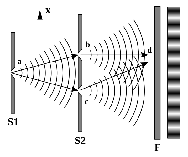
Shine light through two very narrow parallel slits onto a screen. Ray optics predicts two bright lines.
What you get is a row of bright and dark bands spread across the whole screen. And the dark bands are the impossible part: at those places, light is arriving from both slits, and the result is darkness. Cover one slit and the dark band lights up.
Adding light to light and getting nothing is something rays cannot do and waves do routinely. Chapter 2.4 showed two water waves cancelling where a crest met a trough. This chapter shows light doing it, which is how the question "what is light?" was settled in 1801 — a century before Maxwell explained what was waving.

Coherence: why you cannot do this with two lamps
Before the derivation, one practical point that explains why interference is not part of everyday experience.
Two waves cancel at a point only if they arrive consistently out of step. If their relative phase jitters randomly, then sometimes they add and sometimes they cancel, and the average over any observable time is simply the sum of the two intensities — no pattern at all.
Two separate light bulbs never produce interference, no matter how carefully arranged. Ordinary light comes from countless atoms emitting independently in bursts lasting about 10^{-8} s, so the phase relationship between two sources scrambles a hundred million times a second.
Two waves with a fixed phase relationship are called coherent. There are two ways to get them:
Split one wave. Send the same light through two slits, or reflect it off two surfaces. Whatever the source does, both copies do it together. This is what Young did and what every classical interference experiment does.
Use a laser. Stimulated emission (Chapter 5.6) forces all the atoms to emit in step, giving coherence lengths of metres or kilometres.
Young's double slit
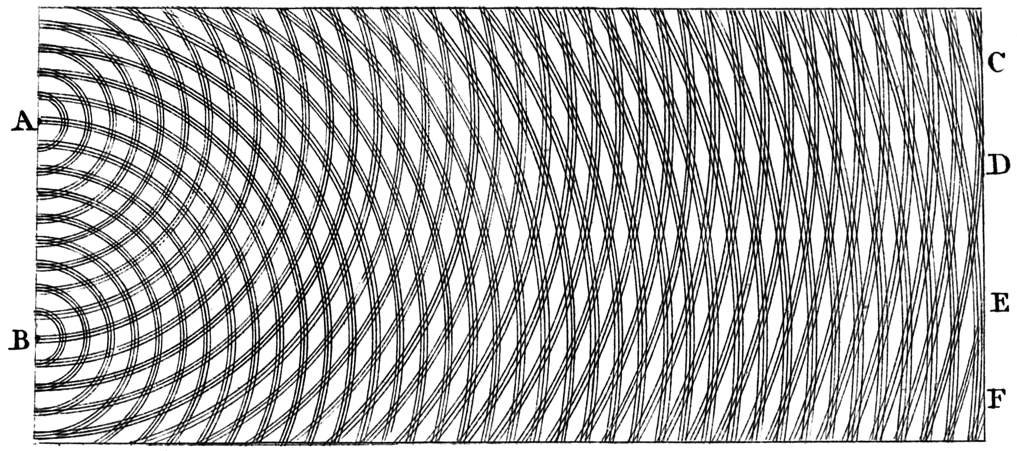
Thomas Young performed the experiment around 1801 and presented it against the full weight of Newton's authority — Newton had argued light was made of particles, and English physics had accepted that for a century. Young was attacked viciously in print. He was right.
The derivation
Two slits separated by d, a screen at distance L, with L \gg d. Consider a point on the screen at angle \theta from the centre line.
Light from the two slits travels different distances to reach that point. The path difference is what matters, and for L \gg d the two rays are essentially parallel, so the geometry is a thin right triangle with the slit separation as hypotenuse:
\Delta = d\sin\theta
Constructive interference — bright band — needs the two waves to arrive in step, which means the path difference must be a whole number of wavelengths:
\boxed{d\sin\theta = m\lambda, \qquad m = 0, \pm1, \pm2,\dots}
Destructive interference — dark band — needs them exactly out of step, a half-integer number of wavelengths:
\boxed{d\sin\theta = \left(m+\tfrac{1}{2}\right)\lambda}
The integer m is the order of the fringe. m = 0 is the central bright band, directly ahead, where the path difference is zero for every wavelength.
For small angles, \sin\theta \approx \tan\theta = y/L where y is the distance up the screen:
y_m = \frac{m\lambda L}{d}
and the spacing between adjacent bright fringes is:
\boxed{\Delta y = \frac{\lambda L}{d}}
Read what that says. Closer slits give wider fringes. A further screen gives wider fringes. Longer wavelength gives wider fringes, so red fringes are more spread out than blue.
Worked example: measuring the wavelength of light
Two slits 0.25 mm apart, a screen 2.0 m away, and the bright fringes measured 4.8 mm apart. What is the wavelength?
\lambda = \frac{\Delta y\, d}{L} = \frac{(4.8\times10^{-3})(0.25\times10^{-3})}{2.0} = \frac{1.2\times10^{-6}}{2.0} = 6.0\times10^{-7}\ \text{m}
600 nm — orange-red light.
This is worth pausing on. We have just measured a length of six ten-thousandths of a millimetre using a ruler. The slit separation and the fringe spacing are both millimetre-scale quantities anyone can measure, and the geometry converts them into a wavelength four thousand times smaller than the smallest thing on the ruler. Young's experiment was the first measurement of the wavelength of light, and it works because interference is an amplifier: it turns a submicroscopic difference in path into a visible displacement of a fringe.
Intensity across the pattern
The bands are not sharp lines with darkness between; the intensity varies smoothly. Adding two waves of equal amplitude E_0 with phase difference \phi:
E_{\text{total}} = E_0\sin(\omega t) + E_0\sin(\omega t + \phi) = 2E_0\cos\left(\frac{\phi}{2}\right)\sin\left(\omega t + \frac{\phi}{2}\right)
using the sum-to-product identity from Volume II, Chapter 3.5. Intensity goes as amplitude squared:
I = 4I_0\cos^2\left(\frac{\phi}{2}\right)
where \phi = \frac{2\pi}{\lambda}d\sin\theta, since a path difference of one full wavelength corresponds to a phase difference of 2\pi.
Two things worth noticing. The maximum is 4I_0, not 2I_0 — four times one slit's intensity, not twice. And the minimum is zero. Energy is not created at the peaks or destroyed at the troughs; it is redistributed, and averaging \cos^2 over the pattern gives exactly 2I_0, which is what two slits should deliver.
The version that broke physics
Run the experiment with the light turned down until only one photon is in the apparatus at a time. Each photon arrives at the screen as a single dot — a particle landing at one place. Let them accumulate for hours.
The interference pattern builds up anyway, dot by dot.
A single photon apparently goes through both slits and interferes with itself. Put a detector at one slit to find out which it took, and the pattern disappears — you get two plain bands, the ray-optics answer. This is not a limitation of the detector; any measurement capable of distinguishing the paths destroys the interference.
The same experiment has been done with electrons, neutrons, whole atoms, and molecules of 2000 atoms. Chapter 7.2 takes it apart properly. It is mentioned here because it is the same apparatus, and because it means the wave picture in this chapter is not the final word — it is a completely accurate description of what light does, resting on a mechanism that is stranger than waves.
Thin films
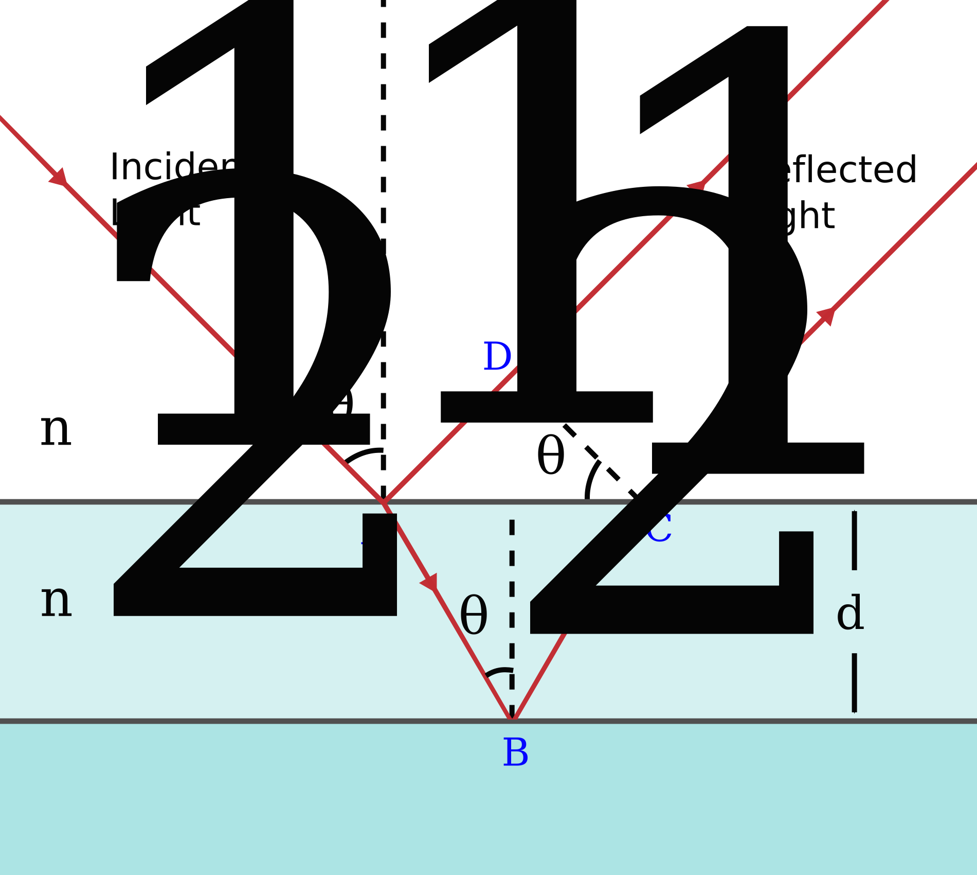
Soap bubbles, oil on a wet road, the colours in a peacock feather, and the coating on your glasses are all the same phenomenon: light reflecting off the two surfaces of a thin layer, and the two reflections interfering.
The phase change on reflection
Before computing anything, there is a rule that catches everyone the first time.
When light reflects off a medium with a higher refractive index, it undergoes a phase change of \pi — half a wavelength. When it reflects off a lower-index medium, there is no phase change.
The mechanical analogy is a wave on a rope. Tie the rope to a wall and send a pulse: it comes back inverted. Attach it to a light thread instead and it comes back the same way up. The reflection off a "harder" medium flips; off a "softer" one it does not. The same result comes out of Maxwell's equations with the boundary conditions applied, and Chapter 4.7's fields are what actually flip.
The condition, derived carefully
Take a soap film of thickness t and index n, in air, viewed at near-normal incidence.
Ray 1 reflects off the top surface, air (n=1) into film (n=1.33). Higher index, so it flips: half a wavelength.
Ray 2 enters the film, reflects off the bottom, film into air. Lower index, so no flip. But it has travelled an extra 2t inside the film, where the wavelength is \lambda/n (Chapter 5.1). Its extra path in wavelengths is 2nt/\lambda.
Total phase difference between the two, in units of wavelength:
\frac{2nt}{\lambda} + \frac{1}{2}
Constructive (bright) needs this to be a whole number:
\frac{2nt}{\lambda}+\frac{1}{2} = m \quad\Longrightarrow\quad \boxed{2nt = \left(m - \tfrac{1}{2}\right)\lambda}
Destructive (dark) needs a half-integer:
\boxed{2nt = m\lambda}
Notice the reversal. Without the phase flip you would expect 2nt = m\lambda to be the bright condition. The single reflection off a denser medium swaps bright and dark, and forgetting it gives exactly the wrong answer every time.
Worked example: the colour of a soap film
A soap film with n = 1.33 appears bright green (\lambda = 550 nm) at normal incidence, in its first order. How thick is it?
2nt = \left(1-\tfrac{1}{2}\right)\lambda = \frac{\lambda}{2}
t = \frac{\lambda}{4n} = \frac{550\times10^{-9}}{4\times1.33} = 1.03\times10^{-7}\ \text{m} = 103\ \text{nm}
A tenth of a micrometre — about a thousandth the thickness of a human hair.
This explains everything you have seen in a soap bubble. The film drains under gravity, so it is thinner at the top and thicker at the bottom, and the colour therefore varies down the bubble in bands. As it keeps draining, the colours march downwards. And just before it pops, the top of the film becomes so thin (t \ll \lambda) that the only phase difference left is the half-wavelength from the reflection — so the two reflections cancel for every wavelength and the top of the bubble goes black. Newton described this black spot in 1704 and it is the reliable warning that the bubble is about to burst.
Oil on water is subtly different. Oil has n \approx 1.45, water n = 1.33. So the top reflection (air to oil, going up in index) flips, and the bottom reflection (oil to water, also going up in index) also flips. Two flips cancel out, and the conditions swap back:
2nt = m\lambda \text{ is bright}, \qquad 2nt = (m+\tfrac{1}{2})\lambda \text{ is dark}
The same physics, opposite answer, and the reason is a single comparison of refractive indices.
Anti-reflective coating
Now use it deliberately. Put a coating of index n_c and thickness t on glass, and choose them so the two reflections cancel.
For the reflections to cancel we want destructive interference in reflection. If 1 < n_c < n_{\text{glass}}, both reflections flip, so the flips cancel and the condition is set purely by path:
2n_ct = \left(m+\tfrac{1}{2}\right)\lambda
The thinnest choice, m = 0:
\boxed{t = \frac{\lambda}{4n_c}}
A quarter-wave coating. For green light at 550 nm and magnesium fluoride, n_c = 1.38:
t = \frac{550\times10^{-9}}{4\times1.38} = 99.6\ \text{nm}
For complete cancellation the two reflections must also be equal in strength, which requires n_c = \sqrt{n_{\text{glass}}} = \sqrt{1.52} = 1.23. No durable material has exactly that index, and MgF₂ at 1.38 is the practical compromise, cutting reflection from 4 % to about 1.3 % per surface.
Why this matters enormously. An uncoated camera lens with seven elements has fourteen air–glass surfaces, each reflecting 4 %. The transmitted fraction is 0.96^{14} = 0.565 — you lose 43 % of the light, and worse, that scattered light bounces around inside the barrel and reduces contrast. With coating at 1.3 % per surface, 0.987^{14} = 0.83. Multi-layer coatings get below 0.2 % per surface across the whole visible band, and modern lenses transmit over 97 %. Complex zoom lenses with fifteen or more elements are simply impossible without coatings, which is why they did not exist before the 1930s.
The coating is tuned for the middle of the spectrum, so red and blue reflect slightly more than green — which is exactly why a coated lens looks purple or blue when you tilt it towards a light.

Structural colour
Some colours in nature have no pigment at all. They are interference, and they behave differently from pigment in a way you can check by eye.
A peacock feather has microscopic layered structures in its barbules; a Morpho butterfly's wing has ridges with regularly spaced lamellae; a beetle's shell has stacked chitin layers. In each case a repeating structure with spacing comparable to the wavelength of light reflects certain wavelengths strongly by interference.
The test is to tilt it. Pigment colour does not change with viewing angle. Structural colour does, because the path difference depends on the angle, so the wavelength that interferes constructively shifts — usually towards blue as you tilt away from normal. A peacock feather changes hue as you turn it. A blue paint does not.
Structural colour never fades, because there is nothing to bleach — the colour is geometry. Beetles in museum drawers keep their colour for two centuries.
And blue is nearly always structural in animals. True blue pigments are rare in biology; almost every blue bird, butterfly and fish is producing blue by structure. Grind a blue feather to powder and it turns brown, because you have destroyed the structure while leaving the melanin underneath. Grind a red feather and it stays red.
Newton's rings and optical testing
Place a slightly curved lens on a flat glass plate. The air gap between them varies from zero at the contact point to larger at the edges, so thin-film interference produces concentric bright and dark rings.
At radius r from the contact point, with lens radius of curvature R, geometry gives the gap as t \approx r^2/2R. With one flip (air-to-glass at the bottom surface of the gap) and none at the top, dark rings occur where:
2t = m\lambda \quad\Longrightarrow\quad r_m = \sqrt{m\lambda R}
The centre is dark, because there the gap is zero and only the phase flip remains.
Newton observed these in 1704 and — awkwardly for his own particle theory — could not explain them without something periodic. He proposed "fits of easy reflection and easy transmission", a wave-like idea he was unwilling to call a wave.
Today the same pattern is a precision instrument. Lay a test optic against a reference flat and count the fringes: each fringe represents a half-wavelength of gap, about 275 nm. A surface flat to one tenth of a fringe is flat to 27 nm. Interference is the standard way to measure anything sub-micrometre, and every telescope mirror, camera lens and semiconductor mask in the world is checked this way.
Interferometers
Push it further and interference becomes the most sensitive measuring technique in physics.
A Michelson interferometer splits a beam in two, sends the halves down perpendicular arms to mirrors, and recombines them. Move one mirror by \lambda/4 and the round-trip path changes by \lambda/2, so bright becomes dark. Counting fringes measures displacement in units of a quarter wavelength — about 150 nm.
Michelson and Morley used one in 1887 to look for the Earth's motion through the ether, and found nothing. Chapter 6.1 tells that story, since the null result is the experimental foundation of relativity.
LIGO is a Michelson interferometer with 4 km arms, and it detects gravitational waves by measuring changes in arm length of about 10^{-18} m — a thousandth the diameter of a proton, and 10^{-22} of the arm length itself. It achieves this by folding the light back and forth in optical cavities so it travels effectively 1600 km, by using very high laser power, and by averaging over many cycles. Chapter 6.10 explains what it is measuring.
Where this shows up in your life
Anti-reflective coating on your glasses, phone screen and camera — the quarter-wave calculation above.
The colours in a CD or DVD are diffraction rather than thin-film, and Chapter 5.4 covers them.
Noise-cancelling headphones are exactly this principle applied to sound: measure the incoming wave, produce one shifted by half a period, and let destructive interference remove it. The reason it works well on low-frequency engine drone and badly on speech is that the cancellation must be accurate to a fraction of a wavelength at the eardrum, which is easy for a 5 m wave and hard for a 20 cm one.
Oil slicks on wet roads show the colours of a film a few hundred nanometres thick, and the bands map the thickness contours.
Fibre-optic sensors built as interferometers monitor strain in bridges, aircraft wings and oil wells, detecting length changes of nanometres over hundreds of metres.
What the next chapter fixes
Interference so far has come from two discrete sources. But a wave passing through a single opening also spreads and interferes with itself, and that self-interference is what stops any optical instrument from being perfect. It sets the smallest detail a microscope can see, the smallest star a telescope can split, the smallest feature a chip factory can print, and the smallest dot a camera can resolve. Chapter 5.4 derives the single-slit pattern, generalises it to circular apertures, and produces the number that limits every imaging system ever built.